Examining available technologies, rules for applying PIVs in commercial HVAC systems
By Brian Venn and Bob Walker
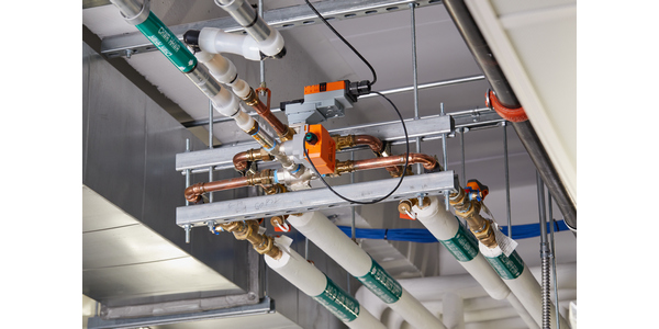
Pressure independent control valves have been specifically designed for commercial HVAC applications since 2003. The following examines the available technologies and rules for applying these valves in a commercial HVAC system.
Why use a PIV in a system? PIVs provide a specific flow for each value of the control signal regardless of the pressure variations in the hydronic system. Eliminating the flow variances due to pressure fluctuations ensures control stability at part loads and prevents overflow in the hydronic loop reducing pump energy and low-differential temperature issues. A PIV replaces the existing control valve and balancing device at the load.
Mechanically regulated PIVs are the marriage of a control valve and a mechanical pressure regulator in one device.
Flow enters through the mechanical regulator followed by the control valve. All PIVs have a minimum (and maximum) differential pressure required to maintain pressure independence. The mechanical regulator is adjusting based on the varying pressures across the valve.
Electronic-pressure independent control valves combine a flow meter, software and control valve.
The ePIV utilizes internal software to position the valve for the required flow as commanded by the temperature control. The characteristic curve for the valve is compared to the actual flow, as read from the internal water flow measurement device. If the flow is outside of the required tolerance, the internal software will reposition the valve to correct the over/underflow.
All PIVs have a minimum (and maximum) differential pressure range required for pressure independent operation (5-50 psid is common). Differential pressures below the required range will result in flows less than design, while pressures above the necessary range will result in flows higher than design. Many manufacturers list differential pressure ranges lower than 5 psid, while remaining pressure independent. Be aware these lower pressures translate to lower flows for an identically sized valve. It is essential to check with the product manufacturer for the proper ranges and associated flows.
Accuracy of pressure independent control valves is generally based on +/- 5% of expected flow due to system pressure fluctuations.
An additional consideration when selecting a PIV is the valve flow characteristic. Should one select an equal percentage flow characteristic or a linear flow characteristic?
The equal percentage flow characteristic is the design choice for matching the valve flow with a hydronic coil to linearize the coil’s output. When the control signal drives the valve to 50%, the output flow is 10-20% of the design flow. When matched with the hydronic coil characteristic, this characteristic results in a linear heat (power) transfer from the coil.
Linear flow characteristics are the design choice used for a bypass valve application. With a 50% control signal, the output flow is 50% of the design flow.
Once in the field, verification is pretty straightforward. An Independent Test and Balance Field Technician would verify the differential pressure across the valve. As stated earlier, this is generally accomplished when 5-50 psi is read across the PICV.
Once confirmed that the correct pressure exists, then the field verification is complete at the load. If the technician cannot verify pressure between the valve differential pressure tolerances, then traditional troubleshooting methods must be fallen back on, like verifying pressure drop across the coil or load is within or close to the rated drop of the coil. An alternative method would be to verify Delta T of Air across the coil, but design conditions must exist for this to give reliable data for troubleshooting.
Properly selected and field-verified PIVs are the hydronic equivalent to pressure independent VAV boxes. PIVs provide both installation and energy savings for the hydronic system reducing both capital and operational expenditures.
Editor’s Note: The information in this article was originally presented in a webinar from the Associated Air Balance Council with Brian Venn, TBE, CxA, Mechanical Testing, Inc. and Bob Walker, CEM, LEED Green Associate, Belimo.


